RI-DMUX
RI-DMUX is a Modbus RTU multiplexer.
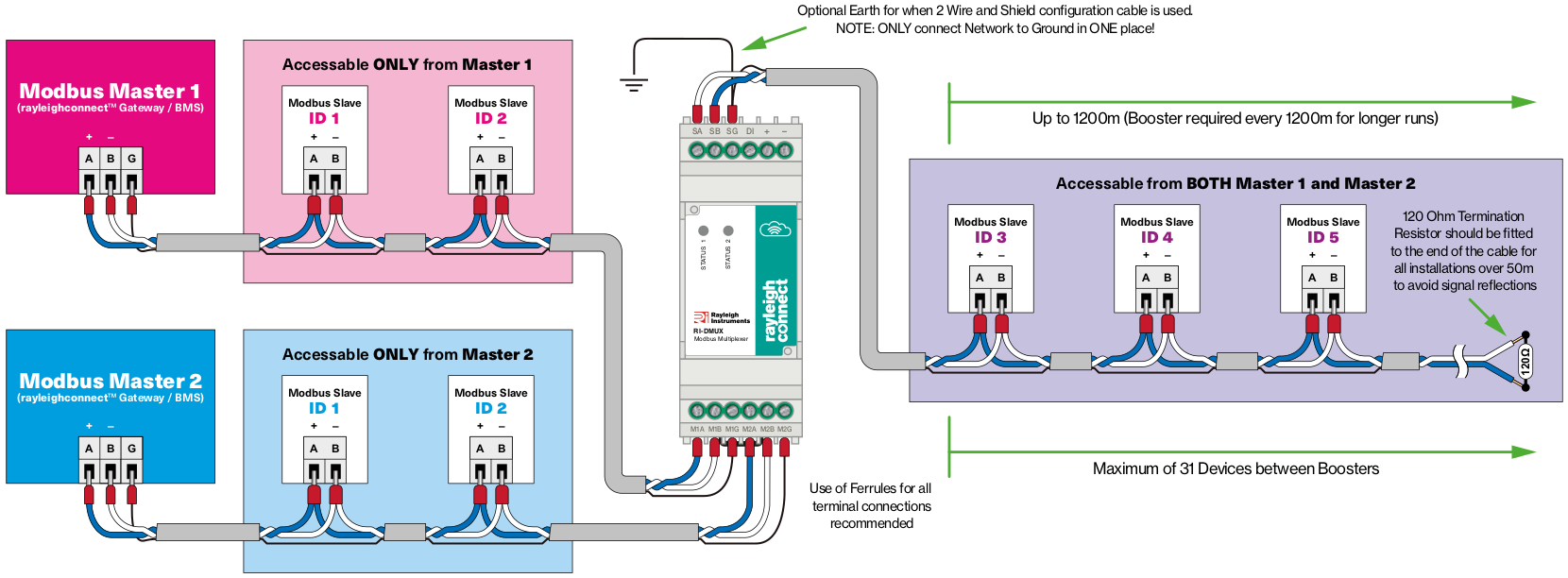
Its main feature is allowing two masters on a single RS-485 bus.
How does it work?
Requests from two Modbus RTU masters are queued and forwarded to Modbus RTU slave devices ensuring no data transmission conflicts. Once response is received it is sent to master that sent the request.
Second master does not receive requests nor responses initiated by first master.
Typical application
Specifications
| Power supply: | Stabilised +5 VDC, min 100 mA |
| Enclosure: | DIN Rail mounted, 2 modules wide (35 mm) |
| Connectors: | Terminal blocks, raster 5.08 mm, 30-12 AWG |
| Operating temperature: | from -20°C to +65°C |
Configuration and registers
Modbus functions
Supported read functions:
- Read Holding Registers (FC=03 —
0x03)
Supported write functions:
- Preset Multiple Registers (FC=16 —
0x10)
Note
Above functions apply to configuration registers only.
RI-DMUX supports forwarding other Modbus RTU functions as well.
Data types
Configuration registers use following data types:
u16- unsigned 16 bit integeru32- unsigned 32 bit integer
Unlocking configuration registers
Making configuration changes requires unlocking the device.
- To unlock the device write maintenance or administration password to
0x000Cregister. - Writing incorrect password to
0x000Cregister will change access level to0(guest).
Reading Enter Password register will return current access level:
| Setting | Default value | Unit | Register Address | Type |
|---|---|---|---|---|
| Enter Password | 0 | enum: 0 - guest 2 - maintenance 4 - administrator |
0x000C | u16 |
Note
Device will automatically return to 0 (guest) access level within 24 hours.
Passwords
Passwords can be changed using following registers:
| Setting | Default value | Register Address | Type |
|---|---|---|---|
| Set maintenance password | 0x0001 | 0x000D | u16 |
| Set admin password | Hidden | 0x000E | u16 |
Unit number
Mobus unit number ("address") is by default set to 252 (0xFC).
Note
Requests sent to this address will not be forwarded to OUT port.
| Setting | Default value | Register Address | Type |
|---|---|---|---|
| Unit number (Address) |
252 (0xFC) |
0x0007 | u16 |
Response delay
| Setting | Default value | Unit | Register Address | Type |
|---|---|---|---|---|
| Minimal response delay | 100 | ms | 0x000B | u16 |
RS-485 port configuration
To change setting of currently used port (IN1 or IN2) use following registers:
| Setting | Default value | Unit | Register Address | Type |
|---|---|---|---|---|
| Baudrate | 9600 | bps1 | 0x0008, 0x0009 | u32 |
| Mode | 1 (8N1) | enum2 | 0x000A | u16 |
1 - Supported baudrate values: 9600, 19200, 38400, 57600, 115200
2 - Mode enum values: 1: 8N1, 2: 8E1, 3: 8O1, 4: 8N2, 5: 8E2, 6: 8O2
Note: When reading the register value, discard the leftmost reserved byte (RRRR MMMM) to get the mode enum value.
Each port can also be configured independently using following registers:
Port IN1 (Master 1)
| Setting | Default value | Unit | Register Address | Type |
|---|---|---|---|---|
| Baudrate | 9600 | bps1 | 0x0140, 0x0141 | u32 |
| Mode | 1 (8N1) | enum2 | 0x0142 | u16 |
| Max wait3 | 2000 | ms3 | 0x0143 | u16 |
| Enable | 1 | enum4 | 0x0144 | u16 |
| Debug messages5 | 1 | enum5 | 0x0145 | u16 |
3 - Max wait specifies how long the IN master waits for the response. Allowed values: 500 – 5000 ms.
For the best performance, max wait should be:
- IN Ports - slightly smaller than a time that a Modbus master waits for the response before sending another request on the given IN port.
- OUT Port - slightly greater than the max response time of the slowest Modbus device connected to the OUT port.
4 - 0: Port disabled (Modbus requests are not forwarded to the OUT port), 1: Port enabled
5 - Debug messages are sent by the RI-DMUX device on behalf of the Modbus target devices to the Modbus masters when the communication with the given Modbus target device is currently not possible. Values:
- 0 – no debug messages, the device just does not respond.
- 1 –
0x06Modbus error code is sent if the OUT port is busy and the Modbus request hasn’t been forwarded. - 2 –
0x0BModbus error code is if the target Modbus device is filtered out.
Port IN2 (Master 2)
| Setting | Default value | Unit | Register Address | Type |
|---|---|---|---|---|
| Baudrate | 9600 | bps1 | 0x0160, 0x0161 | u32 |
| Mode | 1 (8N1) | enum2 | 0x0162 | u16 |
| Max wait3 | 2000 | ms3 | 0x0163 | u16 |
| Enable | 1 | enum4 | 0x0164 | u16 |
| Debug messages5 | 1 | enum5 | 0x0165 | u16 |
Port OUT
| Setting | Default value | Unit | Register Address | Type |
|---|---|---|---|---|
| Baudrate | 9600 | bps1 | 0x0180, 0x0181 | u32 |
| Mode | 1 (8N1) | enum2 | 0x0182 | u16 |
| Max wait3 | 2000 | ms3 | 0x0183 | u16 |
Querying port number
Master can read which port it is connected to by reading following register:
| Setting | Default value | Unit | Register Address | Type |
|---|---|---|---|---|
| Port ID | N/A | enum: 1 - port 1, 2 - port 2 | 0x0100 | u16 |
Port priority
RI-DMUX can be configured to prioritize one of the IN ports.
| Setting | Default value | Unit | Register Address | Type |
|---|---|---|---|---|
| Port priority | 0 (equal) | enum: 0 - equal, 1 - port 1, 2 - port 2 | 0x0101 | u16 |
Modbus filtering
When RI-DMUX receives response on one of the IN ports (instead of OUT port) it will add Modbus unit number (address) to filtering list.
All subsequent requests addressed to filtered devices will NOT be forwarded to OUT port.
This feature enables more advanced RS-485 bus topologies where e.g.:
- only part of RS-485 bus is shared with second master
- each master has private devices, which can use same unit numbers (addresses)
When there is no response from filtered device on any of IN ports for more than 120 seconds it is removed from filtering list.
Filtering time can be adjusted by writing to 0x0103 register.
| Setting | Default value | Unit | Register Address | Type |
|---|---|---|---|---|
| Modbus filtering | 120 | s6 | 0x0103 | u16 |
6 - Allowed values: 10 - 65535
Advanced filtering configuration
We advise to use default automatic filtering.
| Setting | Default value | Unit | Register Address | Type |
|---|---|---|---|---|
| Filter mode | 1 (auto) | enum: 0 - disabled 1 - auto 2 - manual |
0x0102 | u16 |
Note
Automatic filtering is supported for function codes 0x03, 0x04 and 0x10 only.
However if required, filtering can be configured manually using 256 bit mask to mark units that should be filtered.
Mask is divided into eight 32 bit registers. E.g.: Writing 0x00000012 to register 0x0104 will disable forwarding of requests to addresses (unit numbers) 0x01 and 0x04.
| Setting | Register Address | Type |
|---|---|---|
| Filter mask | 0x0104 | u32 |
| Filter mask | 0x0106 | u32 |
| Filter mask | 0x0108 | u32 |
| Filter mask | 0x010A | u32 |
| Filter mask | 0x010C | u32 |
| Filter mask | 0x010E | u32 |
| Filter mask | 0x0110 | u32 |
| Filter mask | 0x0112 | u32 |
Note
In automatic mode filter mask registers can be read to view current filtering status.
Modbus statistics
RI-DMUX provide following bus statistics that can be used in troubleshooting.
Each register contains count of messages (requests or responses).
Note
Statistics reset every 24 hours.
Port IN1
| Message type | Register address | Type |
|---|---|---|
| Correct | 0x01A0 | u16 |
| Filtered | 0x01A1 | u16 |
| Rejected | 0x01A2 | u16 |
| Invalid request | 0x01A3 | u16 |
| Invalid response | 0x01A4 | u16 |
| No response | 0x01A5 | u16 |
Port IN2
| Message type | Register address | Type |
|---|---|---|
| Correct | 0x01B0 | u16 |
| Filtered | 0x01B1 | u16 |
| Rejected | 0x01B2 | u16 |
| Invalid request | 0x01B3 | u16 |
| Invalid response | 0x01B4 | u16 |
| No response | 0x01B5 | u16 |
Device information
| Name | Register Address | Type |
|---|---|---|
| Status 1 | 0x0000 | u16 |
| Status 2 | 0x0001 | u16 |
| Protocol version | 0x0002 | u16 |
| Serial number | 0x0003, 0x0004 | u32 |
| Hardware version | 0x0005 | u16 |
| Firmware version | 0x0006 | u16 |
Factory reset
Warning
Writing to (or reading from) this register will reset the device to factory settings.
| Name | Register Address | Type |
|---|---|---|
| Factory reset | 0x001F | u16 |
Timing over RS-485 with Latency Considerations
Overview
The performance characteristics and timing calculations for Modbus RTU communication over RS-485 include:
- Modbus RTU frame construction
- Request-response timing at various baud rates
- Impact of hardware-induced delays (slave processing and converter buffering)
- Practical recommendations for optimizing performance
Setup Description
Consider typical system with single Master:
sequenceDiagram
    participant Master1 as Master 1
    participant Converter as RI-DMUX
    participant Remote as Modbus Slave

    Master1-->Converter: RS-485 Port IN1

    Master1->>Converter: Request to Slave Device
    activate Master1
    activate Converter

    Converter-->Remote: RS-485 Port OUT

    Converter->>Remote: Request to Slave Device
    activate Remote

    Converter-->Remote: Request processing time
    opt
        Converter-->Remote: Response delay<br>(default depends on device model)
    end

    note over Converter,Remote: #9888;<br>Port OUT Max Wait configuration<br>may require adjusting.<br>(default: 2000 ms)

    Remote->>Converter: Response from Slave Device
    deactivate Remote

    opt
        Converter-->Master1: Response delay<br>(default: 100 ms)
    end

    note over Converter,Master1: #9888;<br>Port IN1 Max Wait configuration<br>must match Master timeout.<br>(default: 2000 ms)

    Converter->>Master1: Response from Slave Device
    deactivate Master1
    deactivate Converter
Example operation:
- Master: Sends a Modbus RTU request using Function Code
0x03(Read Holding Registers). - Slave: Adds a 100 ms processing delay before responding.
- RI-DMUX: Introduces an additional 100 ms delay before forwarding the slave's response back to the master.
- Protocol: Modbus RTU, 8N1 format (1 start bit, 8 data bits, 1 stop bit).
- Register Count: 128 registers (256 bytes of data).
Modbus RTU Request Details
To read 128 registers starting at address 0x0000 from unit ID 1, the command is:
01 03 00 00 00 80 C4 0B
| Field | Description |
|---|---|
01 |
Slave Address |
03 |
Function Code (Read Holding Reg) |
00 00 |
Start Address |
00 80 |
Quantity of Registers (128) |
C4 0B |
CRC16 (Lo Hi) |
| Length | 8 bytes total |
Response Frame
The expected response includes:
- 1 byte slave address
- 1 byte function code
- 1 byte byte-count field (256)
- 256 bytes of register data
- 2 bytes CRC
Total size: 261 bytes
Request-Response Timing by Baud Rate
Each byte (in 8N1 format) transmits as 10 bits. Time per byte = 10 / Baud Rate.
| Baud Rate | Byte Time (ms) | Request (8B) | Response (261B) | Inter-frame Gap | Ideal Total Time |
|---|---|---|---|---|---|
| 9600 | 1.0417 | 8.33 ms | 271.88 ms | 3.65 ms | ~284 ms |
| 19200 | 0.5208 | 4.17 ms | 135.94 ms | 1.82 ms | ~142 ms |
| 38400 | 0.2604 | 2.08 ms | 67.97 ms | 0.91 ms | ~71 ms |
| 57600 | 0.1736 | 1.39 ms | 45.32 ms | 0.61 ms | ~47 ms |
| 115200 | 0.0868 | 0.69 ms | 22.66 ms | 0.30 ms | ~24 ms |
These are ideal-case numbers assuming no hardware latency and immediate response.
With Real-World Latency
Now consider:
- 100 ms slave processing delay
- 100 ms RI-DMUX buffering delay
Total Transaction Time at 9600 bps
| Component | Time |
|---|---|
| Master transmit | 8.33 ms |
| Slave processing | 100 ms |
| Slave transmit | 271.88 ms |
| Converter delay | 100 ms |
| Inter-frame gap | 3.65 ms |
| Total | ~484 ms |
Total at 19200 bps
| Component | Time |
|---|---|
| Master transmit | 4.17 ms |
| Slave processing | 100 ms |
| Slave transmit | 135.94 ms |
| Converter delay | 100 ms |
| Inter-frame gap | 1.82 ms |
| Total | ~342 ms |
Throughput Implications
| Baud Rate | Max Transactions/sec (ideal) | Max Transactions/sec (with delays) |
|---|---|---|
| 9600 | ~3.5 | ~2.0 |
| 19200 | ~7.0 | ~2.9 |
| 38400 | ~14.0 | ~3.8 |
| 115200 | ~41.6 | ~5.4 |
The 200 ms artificial latency limits scaling, even at high baud rates.
Recommendations
- Use higher baud rates to minimize protocol overhead.
- Avoid large register reads if system introduces latency — break requests into smaller blocks (e.g., 64 registers).
- Tune slave firmware to reduce processing delay, if possible.
- Reduce RI-DMUX delay configuration if delay is not needed.
Timeout Scenario: Slave Not Present or Unresponsive
When a slave device is not present on the RS-485 bus or fails to respond (e.g., due to power failure, configuration error, or hardware fault), the Modbus master waits for a response until the configured timeout elapses. In most systems, this timeout is set to 2000 ms (2 seconds) by default.
In such cases:
- The master blocks for 2000 ms, expecting a reply that never arrives.
- No useful data is returned, and a timeout exception or error code is typically triggered in the SCADA/HMI/logging system.
- The transaction time balloons from hundreds of ms to 2 seconds, severely degrading throughput if retries or polling continue.
- If multiple unresponsive devices are polled sequentially, this can cascade into seconds of wasted time per cycle.
Impact
At 9600 baud with a 2-second timeout per failure, polling just five missing slaves could waste 10+ seconds, severly reducing maximum polling rate.
Multi-master operation
All considerations above apply to multi master operation:
sequenceDiagram
    autonumber

    participant Master1 as Master 1
    participant Master2 as Master 2

    participant Converter as RI-DMUX
    participant Remote as Modbus Slave


    Master1->>Converter: Request to Slave Device
    activate Master1
    activate Converter
    Note left of Converter: RS-485 Port IN1

    Converter->>Remote: Request to Slave Device
    activate Remote
    Note right of Converter: RS-485 Port OUT

    Master2-->>Converter: Request to Slave Device
    activate Master2
    Note left of Converter: RS-485 Port IN2

    Remote->>Converter: Response from Slave Device
    Note right of Converter: RS-485 Port OUT
    deactivate Remote

    Converter->>Master1: Response from Slave Device
    Note left of Converter: RS-485 Port IN1
    deactivate Master1

    Converter-->>Remote: Request to Slave Device
    activate Remote
    Note right of Converter: RS-485 Port OUT
    Remote-->>Converter: Response from Slave Device
    Note right of Converter: RS-485 Port OUT
    deactivate Remote
    Converter-->>Master2: Response from Slave Device
    Note left of Converter: RS-485 Port IN2
    deactivate Master2
    deactivate Converter